



Overhead distribution systems operate in environments where reliability can be challenged by everything from severe weather events and wildfires to vegetation and limited rights of way. Addressing those challenges requires looking beyond any single component and considering how the entire system can be strengthened against the conditions that commonly lead to outages.
For utilities, system hardening is increasingly about building resilience before an event occurs. That means identifying where infrastructure may be more vulnerable, understanding the risks affecting individual circuits, and determining which mitigation strategies can provide meaningful improvements in reliability.
At the same time, every hardening decision must balance performance with practical considerations, such as cost, permitting, construction requirements, and project timelines. The challenge is not simply determining how to strengthen the grid, but how to make targeted investments that address risk while remaining practical to implement.
American Wire Group’s AerialGuard® System Solutions bring these elements together through tree wire and spacer cable, along with the hardware and accessories required to build a complete system. Understanding how these components work together, and the options available within the cable design, can help utilities determine the right approach for their distribution needs.
Building Reliability into the System
For utilities, system hardening is not simply about responding more effectively after an outage occurs. It is about strengthening infrastructure to better withstand the conditions that can lead to outages in the first place.
Every distribution environment presents different challenges. In some areas, vegetation may be a primary concern, while utilities in other areas may be addressing wildfire risk, severe weather, space limitations, or the need to strengthen infrastructure against potential outages.
Vegetation and other incidental contact can create faults, flashovers, outages, and system damage when objects come into contact with bare overhead conductors. During severe weather, falling limbs can introduce additional electrical and mechanical stress, increasing the potential for outages or damage to overhead infrastructure.
By identifying higher risk circuits and addressing their specific vulnerabilities, utilities can take a more targeted approach to improving system reliability.
Addressing Storm and Wildfire Risk
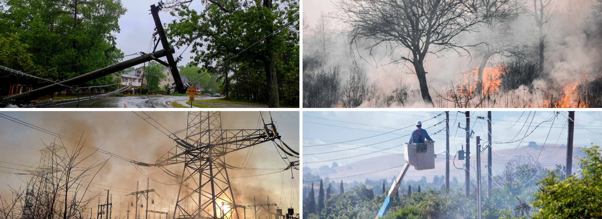
Severe weather and wildfire conditions highlight the importance of building reliability into distribution infrastructure before a weather event occurs. These weather events can place significant stress on overhead infrastructure, potentially resulting in contact related faults, damaged equipment, or downed conductors.
These concerns can become even more consequential where wildfire risk is present. Vegetation contact, electrical faults, arcing, and energized downed conductors can create serious hazards during dry or elevated fire conditions. Reducing the likelihood for these events is an important consideration within broader wildfire mitigation and resiliency strategies.
The challenge is determining how to address these risks in a way that is both effective and practical. Undergrounding can reduce exposure to many overhead hazards, but its higher cost, permitting requirements, construction complexity, and project timelines can make it impractical as a universal hardening strategy.
For utilities balancing system risk with available capital, this makes targeted investment especially important. Underground construction can be prioritized where system conditions or potential consequences justify the additional investment, while overhead hardening strategies can provide a more cost-effective approach across other portions of the system.
The Economic Value of Improved Reliability
The value of system hardening extends beyond reducing exposure to storms and wildfires. Improvements in reliability can also deliver measurable economic benefits by reducing the frequency and duration of outages, limiting restoration expenses, emergency crew deployments, equipment repairs, and the financial impact of customer interruptions.
Utilities can assess these benefits through established performance metrics, such as the System Average Interruption Frequency Index (SAIFI) and System Average Interruption Duration Index (SAIDI).
The benefits of covered conductor systems are supported by real-world utility experiences. The U.S. Department of Energy’s Utility Wires Investments Resilience Investment Guide highlights PacifiCorp’s experience with spacer cable, reporting an approximately 90% reduction in tree-related customer interruptions. This demonstrates the potential for covered conductor systems to reduce contract-related outages and the operational burden associated with restoring service.
The financial case is further supported by infrastructure investment comparisons. California Public Utilities Commission records cite Southern California Edison (SCE) installation costs of approximately $438,000 per mile for covered conductors with hardened poles, compared to $3 million per mile for underground construction in fire threatened areas. SCE also concluded that each dollar invested in covered conductor reconductoring delivered more than four times the wildfire risk mitigation value of a dollar invested in underground conversion.
Together, these findings demonstrate why hardening investments should be evaluated beyond upfront material costs. By considering reduced outage exposure, restoration expenses, avoided customer interruption costs, and long-term reliability improvements, utilities can better assess the lifecycle value of infrastructure upgrades and prioritize investments where they can deliver the greatest benefit.
Maximizing System Hardening Investments
By adding a protective covering to the conductor, these systems can help reduce the likelihood that incidental contact with vegetation, wildlife, or other objects develop into a fault, flashover, or outage.
For circuits where vegetation, severe weather, wildfire exposure, or other operating conditions warrant additional protection, covered conductors can strengthen overhead infrastructure without the cost, permitting requirements, and construction timelines associated with moving the circuit underground. It does not replace undergrounding in every application, but provides utilities with another option for allocating hardening investments based on the risk, requirements, and economics of each circuit.
The economics of a covered conductor project extend beyond the conductor itself. A complete system would also require a messenger, spacers, brackets, insulators, dead-end components, and other supporting hardware. When these components are sourced separately, utilities may face additional procurement activity, engineering coordination, supplier management, material compatibility considerations, and schedule risk.
American Wire Group’s (AWG) AerialGuard® System Solutions addresses the project as a complete system, bringing together covered tree wire or spacer cable with the hardware and accessories required for the installation. Sourcing these components through a single provider can simplify specification, procurement, material coordination, and delivery while reducing the number of supplier interfaces that must be managed throughout the system hardening upgrades.
By combining the capital efficiency of targeted overhead hardening with a coordinated, single source system approach, AerialGuard® can help utilities address both the infrastructure risk and project execution considerations within the same hardening investment.
It is also important to remember that covered conductors are installed and treated as an uninsulated conductor. Its covering does not change how the conductor is handled from a safety perspective, but provides another level of protection against certain types of incidental contact.
AerialGuard® Tree Wire and Spacer Cable: Understanding the Difference
AerialGuard® tree wire and spacer cable are both covered conductor solutions used in overhead distribution networks, but their system configurations differ.
Tree wire is designed to replace bare overhead conductors and is typically installed in the same flat or nearly flat configuration as the conductor it replaces. In many applications, the same conductor construction can be used with the addition of the protective covering, allowing utilities to strengthen an existing overhead configuration without fundamentally changing how the circuit is arranged. Larger or stronger conductor materials, such as ACSR, can also be used depending on system requirements.
Spacer cable uses a more compact approach. The conductors and messenger are arranged with uniform spacing in a diamond configuration maintained by spacer hardware. The complete cable and spacer assembly is typically supported by an aluminum clad steel messenger. The messenger plays an important role beyond supporting the assembly. Its higher tensile strength compared with the aluminum phase conductors helps the system withstand mechanical loading events, such as branch contact, reducing the potential for the circuit to be brought down. It also provides a path to ground for the circuit.
This compact configuration allows spacer cable systems to occupy minimal space, making it useful where rights of way are limited or multiple circuits must operate within constrained corridors.
Both configurations demonstrate an important point: the cable is only one part of an overhead distribution system. While tree wire offers a familiar configuration for replacing bare conductors, spacer cable provides a coordinated system designed around the conductor, messenger, spacers, and supporting hardware.
Understanding Cable Construction and Covering Options
The construction of the covered conductor itself also provides flexibility for different product requirements.
AerialGuard® tree wire and spacer cable is available for 15 kV, 25 kV, and 35 kV aerial distribution systems, with additional constructions available for other system voltages. Conductor options include AAC, AAAC, ACSR, ACSR/AW, and AS/AC.
The cable uses a three-layer construction consisting of a conductor shield, inner covering, and track-resistant outer covering. Both thermoplastic polyethylene (PE) and thermoset crosslinked polyethylene (XLPE), covering systems are available.
Choosing between PE and XLPE depends on the application and system requirements. Both provide viable solutions, but XLPE offers enhanced characteristics for projects where thermal and mechanical performance are priorities.
The crosslinking process changes how polyethylene responds to heat. Unlike thermoplastic PE, which can soften when exposed to sufficiently elevated temperatures, XLPE is a thermoset material and provides greater resistance to melting and deformation. Its construction can also provide advantages where tensile loading, thermal resistance, and demanding environmental conditions are important considerations.
Understanding these differences allows utilities to consider covering material as part of the overall system design and operating environment rather than simply as a cable specification.
Completing the System with Hardware and Accessories
A properly designed aerial system depends on all the components working together to provide the intended electrical and mechanical performance.
With spacer cable in particular, the messenger, spacers, brackets, insulators, and supporting hardware all have specific purpose. Spacers maintain conductor positioning and the compact diamond configuration, while brackets support the system across different line configurations. Insulators and related hardware provide additional electrical and mechanical support throughout the installation.
This makes considering and selecting hardware an important part of system planning rather than something that comes after the cable has been specified. The performance of the system ultimately depends on how its individual components work together in the field.
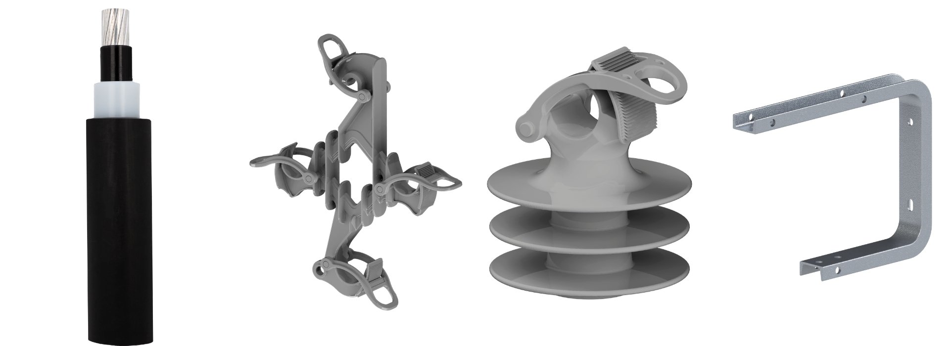
A complete AerialGuard® system can incorporate spacers, tangent and angle brackets, anti-sway brackets, dead end brackets and insulators, polymeric pin insulators, insulator pins, thimble clevises, and other supporting hardware. Bundling these components alongside the conductor helps create a more cohesive system from specification through installation.
Simplifying a Complete System from Planning through Installation
Building an effective tree wire or spacer cable system requires more than identifying the appropriate conductor. The messenger, spacers, brackets, insulators, and other hardware must also be considered part of the overall design.
That coordination becomes particularly important when utilities are planning hardening upgrades. Material availability, compatible components, delivery timing, and installation requirements can all affect how efficiently a project moves from specifications to construction.
Approaching these components as one integrated system can simplify that process. Coordinating the conductor and supporting hardware from the outset provides greater visibility into what is required from the complete installation and helps keep material planning aligned with project schedules.
For utilities managing long-term infrastructure, that system approach can also reduce the complexity of sourcing individual components separately while helping ensure the materials required for an installation are considered together.
AWG is Your Single Source Solution Provider
Selecting the right conductor is important but creating an effective tree wire or spacer cable installation means considering every component that supports it.
When cable, spacers, brackets, insulators, messenger components, and supporting hardware are designed and specified as part of the same system, sourcing those components together can simplify specification, procurement, and project coordination.
American Wire Group’s AerialGuard® System Solutions provide the tree wire and spacer cable, hardware, accessories, and technical support needed to approach aerial distribution as a complete system. With multiple conductor constructions, PE and XLPE covering options, and components designed for different system configurations, utilities can build an AerialGuard® solution around the requirements of each application.
From everyday reliability and constrained rights of way to storm hardening and wildfire mitigation, taking a complete system approach helps ensure every component is working toward the same goal: a stronger, more resilient distribution system.
Contact us to start building reliability into your system.
Comments are closed